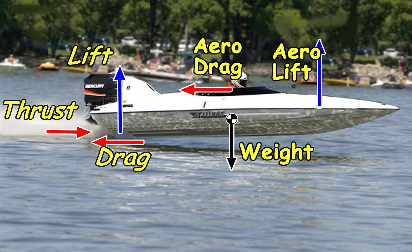
Figure 1 - Aerodynamic and Hydrodynamic forces combine to balance
the hull; and it is a different balance at every velocity.
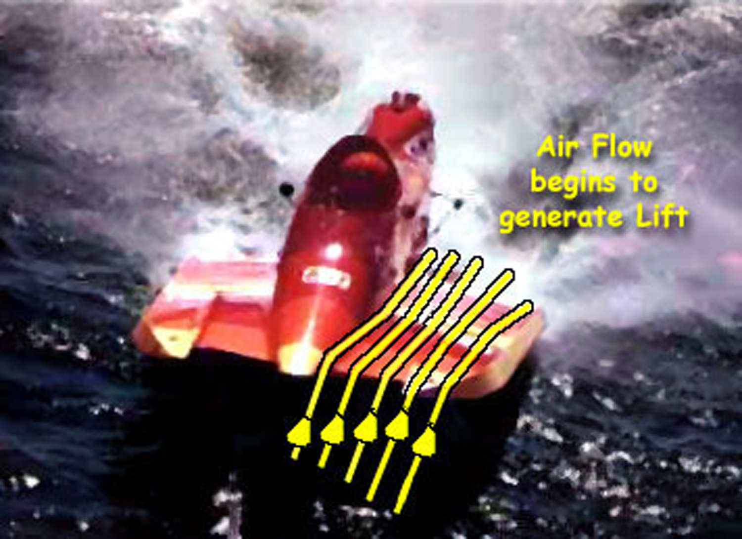
Figure 2 – Tunnel hulls see a unique balance between aerodynamic
Lift generated by the deck and or tunnel configuration, and the
hydrodynamic Lift generated by the sponson surfaces.
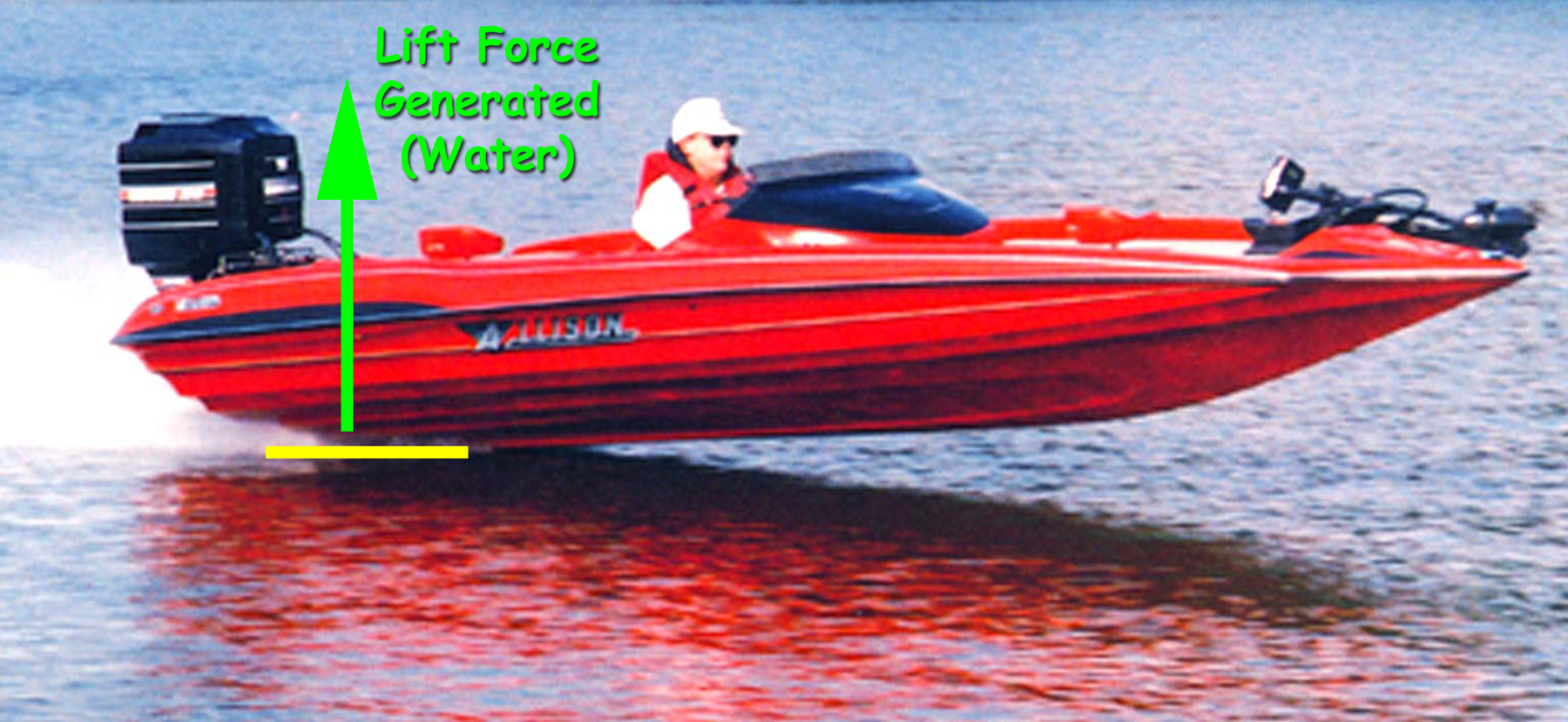
Figure 3 – Vee-pad hulls transition to significant Lift
generated by highly efficient aftward “pad” at higher
velocities.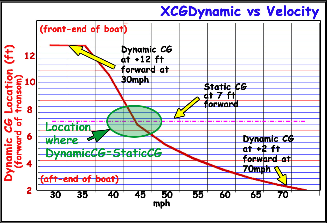
Figure 4 – Vee-pad hulls transition to significant Lift
generated by highly efficient aftward “pad” at higher
velocities.
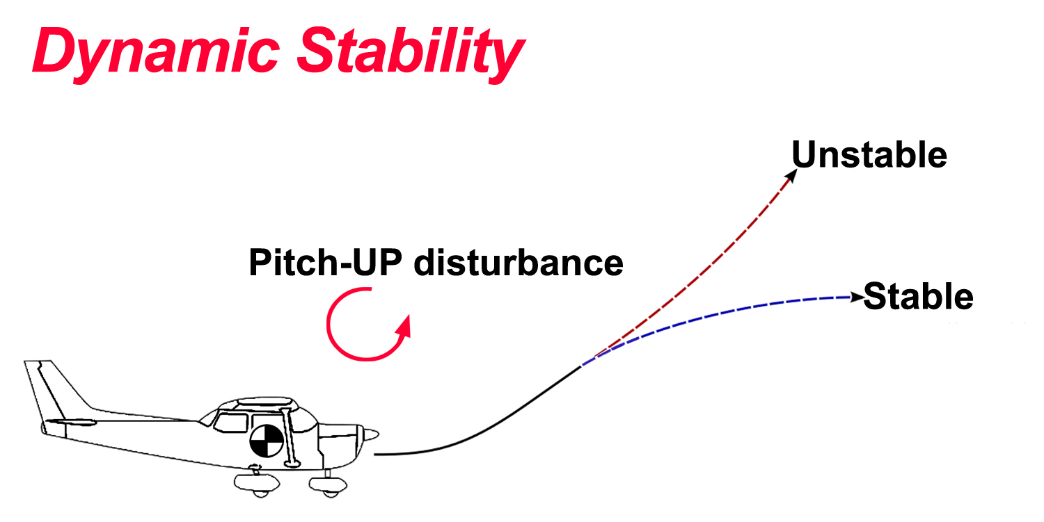
Figure 5 – An airplane is 'inherently stable', since a
slight raising of the nose results in a self-correcting nose-down
moment.

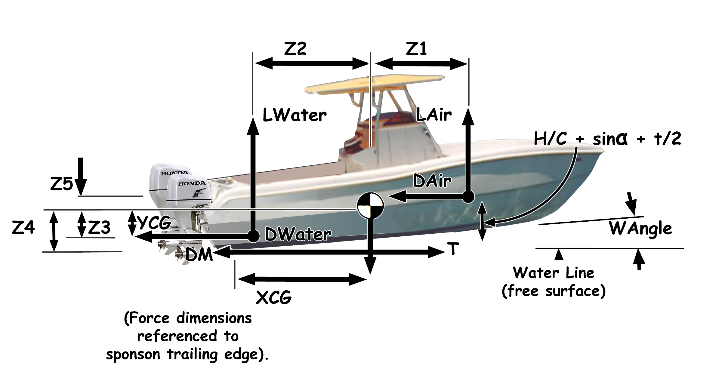
Figure 6 – All boats are
treated the same methods for analysis and balance of static and
dynamic forces.
|
|
Advanced analysis of the changing
hydrodynamic and aerodynamic forces acting on tunnel hulls and vee
hulls gives highly accurate dynamic stability, performance predictions &
optimization.
Jim Russell applies these advancements
in newest versions of AR's
TBDP©/VBDP© performance analysis software.
Background...
The 'Static CG' of a hull is the location of balance of the hull,
appendage and payload deadweights
while boat is at rest.
But this is a small part of the important balance of a performance
hull - particularly since the performance boat usually operates
at velocities greater than zero!
The combined center of ALL the lift forces
and all the drag forces (sponsons, center-pod, vee surfaces, center-pad,
aerodynamic surfaces, lower unit, etc.) while a boat is under way,
is called the 'Dynamic Center of Forces' or 'xCFDynamic'. The 'xCFDynamic' location changes throughout the operating velocity range and
is the most important design measure to consider when 'balancing'
a performance boat.
Note that this method applies EQUALLY to
all styles, sizes, configurations of hulls, and for all weights,
power and velocities - just the same analysis.
How it Works...
Lift = Weight = Performance - All boats must generate enough
lift to balance the weight of the hull. Performance tunnel and vee
hulls generate lift by hydrodynamic 'planing' surfaces and aerodynamic
surfaces. As a boat goes faster it needs less wetted surface to
generate it's required Lift – but that Lift is always equal
to the weight of the boat – and the Lift always comes with
a certain amount of drag.
Tunnel hulls
see a unique balance between aerodynamic Lift generated by the deck
and or tunnel configuration, and the hydrodynamic Lift generated
by the sponson surfaces on the water.
Vee hulls (and Vee-Pad hulls) gain lift from
the balance of lift from planing vee surfaces and/or center-pad
surfaces and also from aerodynamic surfaces.
Tunnel hulls...
As the hull velocity
changes, so does the source and location of lifts and drags. For
example, a typical high-performance sport tunnel hull will, at lower
speeds, see most of its Lift generated by a length of planing sponson
pads, with the center of Lift located well forward. As speed increases,
aerodynamic lift generated by the deck and tunnel configuration
becomes more significant, allowing the sponson wetted surface area
to decrease to only the aft-most parts of the sponson pads. The
hull is now supported by the hydrodynamic Lift from a small aftward
surface of the sponsons, combined with the aerodynamic Lift from
deck/tunnel surfaces - and the overall center of Lift now located
well to the aft of the boat.
Dynamic CG and the Hump Zone...
The “hump zone” for a tunnel hull represents the speed
at which a more significant amount of Lift changes from sponson
lift to aerodynamic lift. Vee hulls see a similar "hump zone"
transition when a more significant amount of Lift changes from vee
surfaces lift to aerodynamic lift and/or vee-pad lift. This "hump"
or "transition zone" occurs at a different velocity with
each boat and setup.
The change in location of the center of Lift
(with increasing velocity) is often quite dramatic, moving from
initially, well forward of the hull’s center of gravity, to
later, well aft of the CG – and causes the onset of potential
instabilities - like Porpoising or chinewalking.
The point (velocity) of instability is
somewhat difficult to predict - but we have a mathematical
method to accurately predict the onset of instability and the
point of the 'Hump Zone Transition".
TBDP©/VBDP©
software
analyzes
d(CFDynamic,
V) and
d(SWet, V)
to determine the velocity range of onset of "Hump
Transition zone".
Inherent Instability...
Any vehicle in 'flight', such as an airplane
or a high performance powerboat, will experience minor changes to
the forces that act on it, and to its speed. If such a change tends
to restore the vehicle to its original speed and orientation, then
the vehicle is said to be “inherently stable”.
If such a change tends to drive the vehicle away from its original
speed and orientation, the vehicle is said to be “inherently
unstable”.
An airplane is 'inherently stable',
since a slight raising of the nose results in a self-correcting
nose-down moment [see Figure 5]. Performance powerboat hulls
are all 'inherently unstable" ‑ that is, a slight
raising of the bow at high speed will usually result in a bigger
raising of the bow, and soon, the boat can become unmanagable.
 This
isn't necessarily a big problem for most boats. Consider that
we could try to balance a pencil on the end of our finger.
It's possible to get it to balance - it's just that any small disturbance
is likely to upset the pencil, causing it to fall. This setup
is 'inherently unstable'. This
isn't necessarily a big problem for most boats. Consider that
we could try to balance a pencil on the end of our finger.
It's possible to get it to balance - it's just that any small disturbance
is likely to upset the pencil, causing it to fall. This setup
is 'inherently unstable'.
We can always balance all of the acting forces
on a boat so that total Lift balances total Weight. The boat may
still be 'inherently' unstable, but we can design a performance
hull to optimize it's dynamic stabilitly and minimize adverse reactions
to small disturbances (such as waves,
wind gusts, etc.)
Vee Pad hulls...
The similar transition
of the Vee-Pad hull to “running on the pad” can
also cause a dynamic instability. Here, the hump zone represents
the speed at which the amount of Lift from the highly efficient “pad”
section of the hull (aftward, center located, flat planing surface)
becomes significant compared to the Lift generated by the veed (full
length, higher deadrise) portion of the hull. For example, a typical
high-performance Vee-Pad hull will, at lower speeds, see most of
its Lift generated by the higher deadrise vee section through the
length of the hull, with the center of Lift located well forward.
As speed increases, the more efficient Lift generated by the flat,
centrally located pad becomes more important, with the overall center
of Lift shifting to the aft of the boat. This change in location
of the center of Lift is often quite dramatic, moving from initially,
well forward of the hull’s center of gravity, to later, well
aft of the CG. This change can initiate dynamic instabilities.
|
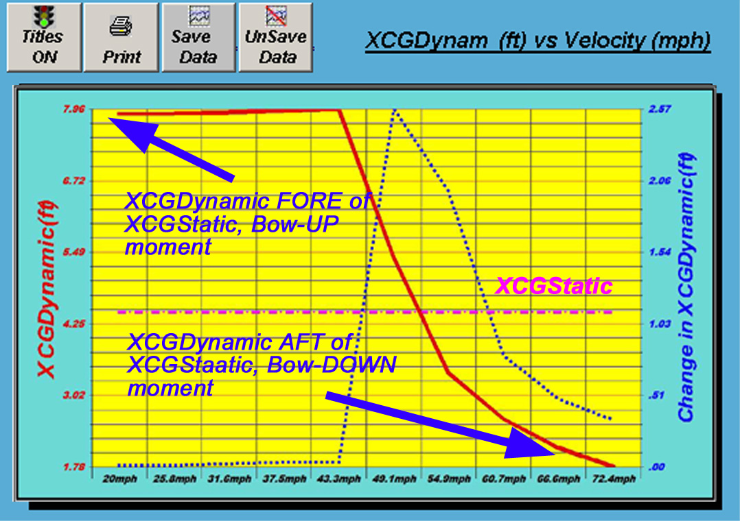
Figure 7 –
The 'Center of Dynamic Forces' location changes dramatically throughout
the operating velocity range of the hull; while the 'Static CG'
of boat remains in the same location.
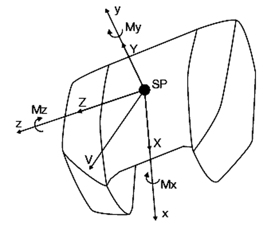
Figure 8 – All 'Dynamic Forces' must be identified and included
in analysis, oriented about 3D axes |
|
Weight Distribution Matters...The distribution of weight in your boat
makes a difference to performance. Proper weight adjustments can
improve or correct handling issues such as porpoising, chine walk
and lower unit blowout. This is important for lateral (side-to-side)
distribution.
Dynamic Balance is key...
The same goes for the fore/aft static
balance, although it's not as easy to know what is just "right"
when the boat is at rest. You
can't balance your boat on the trailer.
All of the lift & drag (hydrodynamic and aerodynamic), thrust
and weight forces on a boat act in different locations - and the
location of each of these forces is constantly changing. (This is
why you can't effectively "balance" your performance hull
while it's still on the trailer). All these different forces at
their different locations combine into a net resultant force that
acts at the dynamic center of Forces (CGFynamic) and represents
the delicate balance of the performance hull.
Ideally, we'd like to have the resultant
of these forces acting at the same location as the Static CG, to
make the boat dynamically ‘stable’. Since the xCFDynamic
location constantly changes throughout the velocity range, this
makes the task of ‘dynamic balance‘ of the hull one
of optimization. Moving weight around can help the boat's balance
in a key velocity range, improving handling and response. The goal
is to move weight so that static CG is closest to the xCFDynamic at the most common or most critical hull speeds.
|
|
Example Analysis
of XCGDynamic & XCGStatic
As an example, let’s consider a small
performance hull with total weight 1600bs and a calculated static
CofG located at XCGStatic=4.5ft forward of the transom. This means
that the weight (1600lbs) of the hull while at rest is centered
at the static center of gravity located +4.5ft ahead of the hull
transom [see Figure 6 above].
Based on the design and setup of this hull
at 20mph, the calculated location of the center of dynamic forces
(XCFDynamic) is approximately +7.8ft fore of transom. This is +3.2ft
FORE of the XCGStatic location, and represents a 'bow-UP' moment
of +5120 lb-ft. If we were going to try to ‘balance’
the hull at just this one velocity (20mph), then we would have to
relocate the static CG location (XCGStatic) FOREWARD by…5120/1600
= 3.2ft FOREWARD from where it is now.
Alternatively, the calculated XCGDynamic
location at 72mph is approximately +1.7ft fore of the transom. This
is -2.8ft AFT of the XCGStatic location and represents a ‘bow-DOWN’
moment of -4480 lb-ft. If we were going to try to ‘balance’
the hull at just this one velocity (80mph), then we would have to
relocate the static CG location (XCGStatic) AFTWARD by -4480/1600
= -2.8ft AFTWARD from where it is now.
The important thing to note with such analysis
is that the static center of gravity (XCGStatic) of the hull obviously
cannot be in two different locations. The important parameter to
study for the performance of the hull is the Dynamic CofG (XCFDynamic),
and XCFDynamic moves to different locations under all the different
operating conditions of the boat. Thus, the hull can, at best, be ‘dynamically
balanced’ at only one velocity. (If we were to move the static
CofG to balance at 20mph, then the ‘dynamic balance’
at 72mph would be worse).
Many of the design features of a hull can
influence the location of the Dynamic CofG (XCFDynamic) throughout
the operating velocity range of the hull. The weight of many of
the payloads of a hull can also be located so as to alter the Static
CofG (XCGStatic). It’s best to try to locate XCGStatic and
XCGDynamic as closely together as possible, and so as to minimize
any dramatic changes in the shifting of XCGDynamic as it relates
to XCGStatic.
An easy way to analyze just how “dramatic”
the changes in shifting XCFDynamic is to plot a graph of
the derivative of the XCGDynamic data…this is the “rate-of-change”
of XCFDynamic…and is shown on the TBDP©/VBDP© graphic
displays as the blue line on the chart. When this curve is increasing,
this means that XCGDynamic is changing at a faster rate. This can
indicate that the hull is becoming more unstable and may be more
difficult for the driver to correct.) See more about “rate-of-change”
graphic curves in Section 7.6.2 of the TBDP/VBDP manual).
This example illustrates the “compromise”
of the design process for performance powerboat hulls. A hull cannot
normally be in ‘dynamic balance’ throughout its operating
velocity range. So, the best approach for the designer is to attempt
to locate the static CofG (XCGStatic) at a location that
helps create the best ‘compromise’ of DYNAMIC BALANCE
at most all speeds in the velocity range, paying particular attention
to the speed regime that will be most utilized by the operators.
|